External LEDs and Push Buttons
EXTERNAL LEDS AND PUSH BUTTONS
Parts List
Laptop
CPX + USB Cable
2 Alligator clips
Push Button
Breadboard
LED (x3 in case you fry some)
Resistor (300 to 1000 Ohms)
Learning Objectives
The VOUT and 3.3V pin are always "ON" even when code is not running on the CPX. So long as your CPX is plugged in via USB or a Lipo Battery
LED are Diodes which means current only flows in one direction
LEDs need resistors in series otherwise they will get too hot and burn up
Breadboard pinout diagrams
Analog pins can be controlled by simply using the digitalio module
LEDs can be hooked up to analog pins and set to blink by changing the board pin
In this project we’re going to use the same blink code as before but modify it to blink an external LED. The purpose of this lab is to familiarize yourself with the pins on the CPX and create a simple circuit using the 5V pin on the CPX and one of the Analog pins. Your laptop has a battery with something between 10 to 20V. There are DC to DC converters in your laptop that provide 5V to your USB ports. These USB ports can be used to power your CPX as you have done in the past few labs.
If you purchased the optional battery pack you can also power the CPX using 3 AA batteries. These batteries nominally have 1.5 V but fully charged it's actually something like 1.8 V. So 1.8 times 3 is 5.4V which is enough to power the CPX. If you have the battery pack and some AA batteries, give it a try. If you still have the blink code from the last project on board you’ll see the D13 LED blink as before. You won’t be able to see the serial print() output as before but that code will be running which is why D13 is blinking. I have noticed that some of the battery packs have power and ground wires swapped. If the battery pack doesn’t work it may be because those two wires are backwards.
The CPX itself uses 3.3V logic which means when it converts numbers to binary a 0 (False) represents 0 volts and a 1 (True) represents 3.3V. The CPX has ports that are labeled various things. GND stands for ground and you need to hook the negative end of your circuit to this and it also has VOUT which supplies 5V to any circuit you build. Hook the positive end of your circuit to the VOUT pin. There is also a port labeled 3.3V and obviously that outputs 3.3V
You’re going to need to use a breadboard so if you’re not familiar with how breadboards work I would recommend watching this video. Your lab today specifically involves an external LED. You can read about LEDs more online if you wish. Remember that the long leg of the LED is the positive end and the short leg is the negative end. The task today is to wire an LED up to the CPX in the following ways
Whenever you modify a circuit on the breadboard, always be sure to remove power from the CPX. You can damage multiple components if you’re not careful.
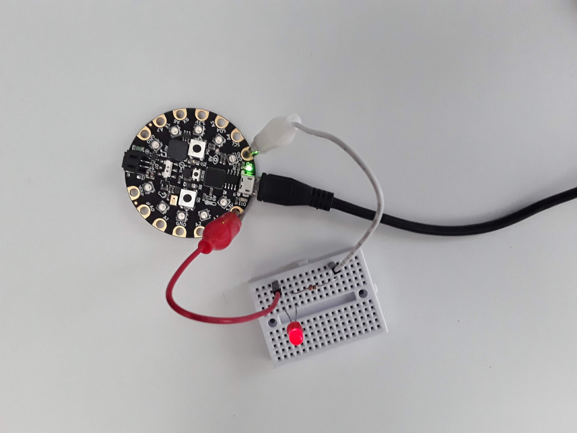
Wire up the circuit with the positive end connected to 5V. This is how my circuit looks. Make sure to use a resistor between 300 and 1000 Ohms. An LED does not have that much internal resistance so you need a resistor in series with an LED to reduce the amount of current flowing through the LED or the entire LED will fry. If you use a resistor that has too much impedance the LED just won’t turn on because the voltage/current through the LED will be below the activation voltage of the circuit.
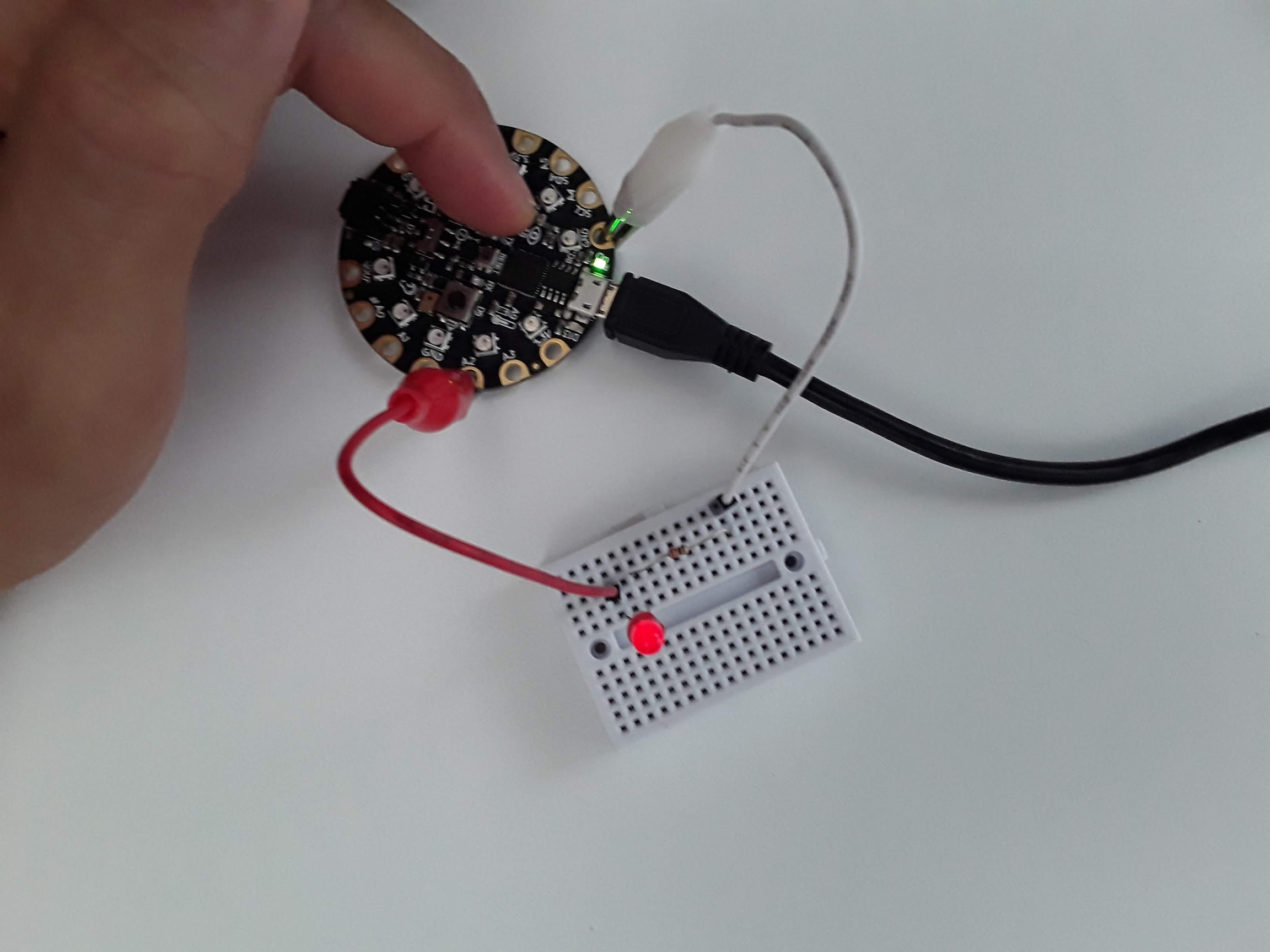
Wire up the circuit again with the 3.3V output. Do you notice anything different when you hook up the circuit with different pins? Here’s my circuit. Do you notice something different about the intensity of the LED? Why is it different?
We’re then going to manually blink the LED using a push button placed onto the breadboard and have it act like a switch. Therefore, when the button is pressed, the LED will turn on and when the button is released the LED will turn off. The button just acts like a wire so you can plug in the button anywhere in the circuit.
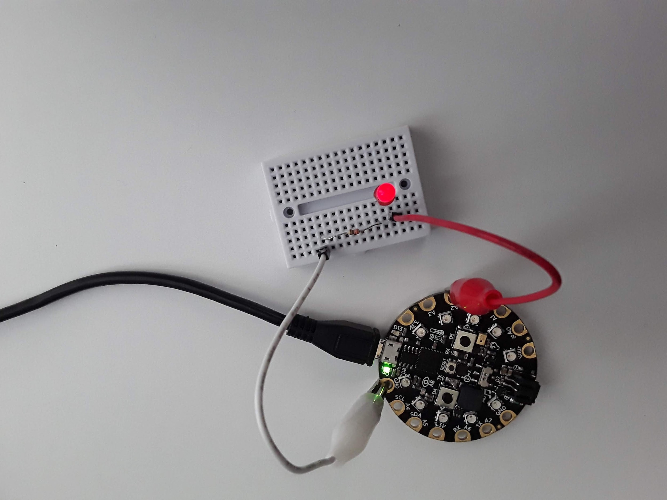
I then want you to hook the positive end of the circuit to pin A2 and then edit your blink code to blink pin A2. Take a look at the blink code. Right now the code is blinking pin D13. How do you think you need to change the code to blink pin A2? Here’s what my circuit looks like for this one. I’ve removed the button since we’re having the CPX act like the button. I won’t include code for this one since you just need to change one line of code.
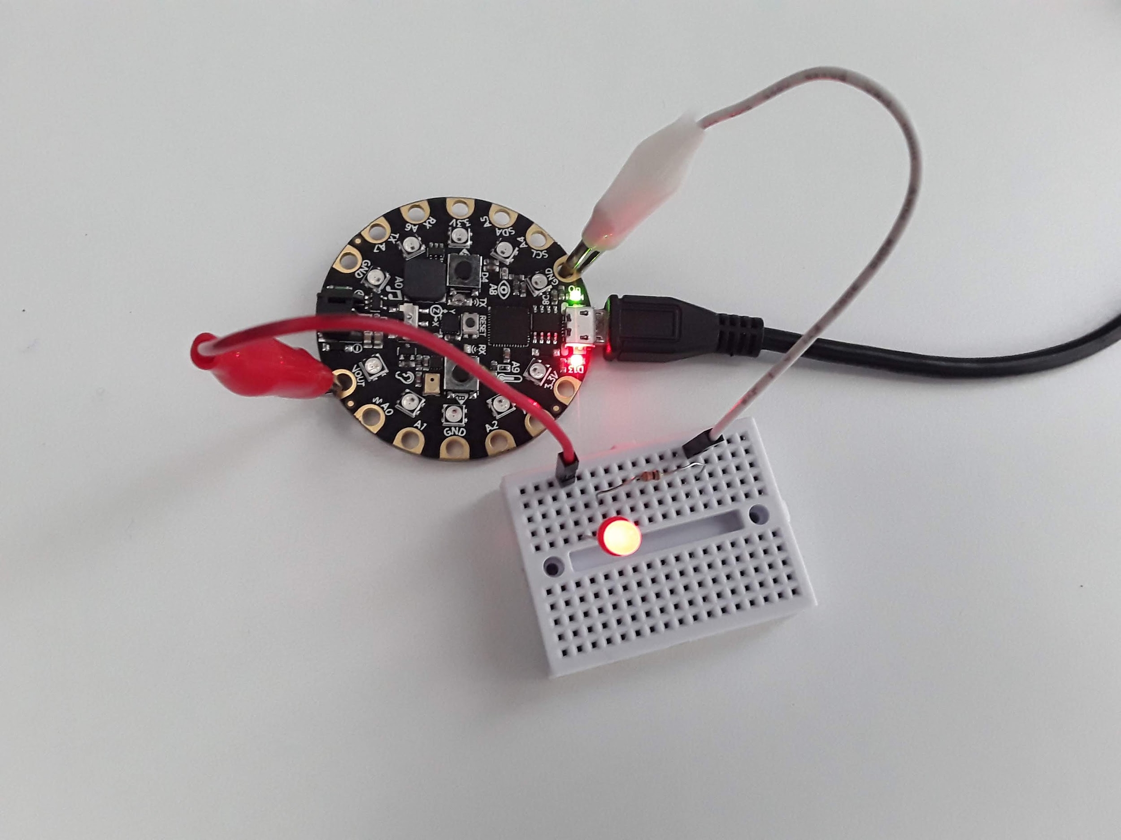
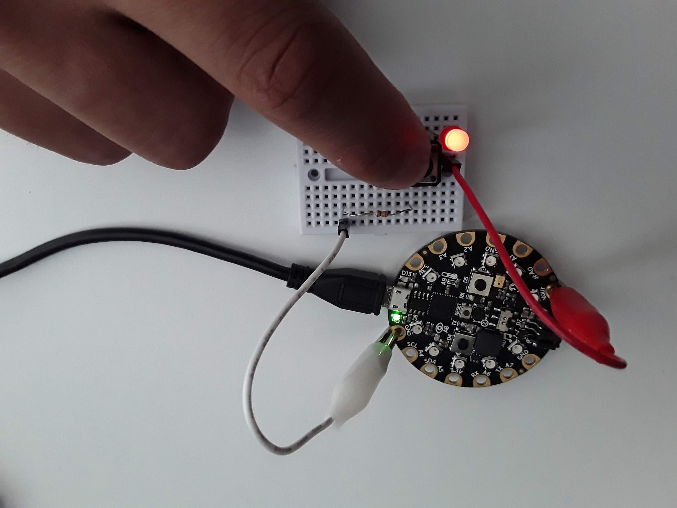
Finally, I want to use one of the buttons on the CPX to blink the LED hooked up to pin A2. So we need to first detect a button press and then tell the program to change the light from True to False depending on what it’s current status is. This one is a bit more difficult so I’ll include the code here and discuss the code itself. Here is my circuit (identical) to the previous one with Button A on the CPX pressed down.
Alright so how do we detect a button press? Well the documentation on this is not so straight forward. What we want to do is detect the INPUT of a digital signal and then do something if we detect that signal. Here’s the code I created to get it to work.
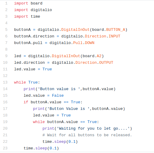
As always this code can be found on my Github. This file specifically is called push_button_external_LED.py. Note if that link ever ends up not working you can easily download the entire Github directory and search for it. So let’s talk about the code.
The first 3 lines are exactly the same as before. Line 5 through 7 are similar to creating the “led” variable except we’re using BUTTON_A as the board value and setting the direction to INPUT. Finally we’re setting the pull direction to DOWN. This means the button acts like a pull down resistor and when it’s pressed the value of the button goes HIGH.
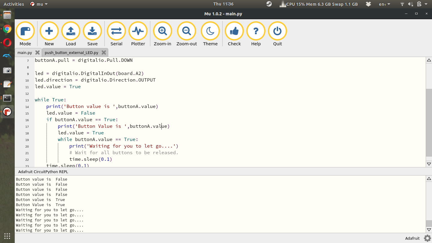
Lines 9-11 are the same as before. We create an led variable and tell the CPX that the led is hooked up to pin A2. We then start the while loop on line 13. First if you click the Serial button you’ll see the text ‘Button value is False’. It’s False because buttonA.value is not being pressed. On line 15 the led is set to False (turned off). On line 16 the button value is checked using an if statement as to whether or not the button is pressed (True). If the button is pressed, the user will be notified that the button is pressed on line 17 and the led will be set to True (on) in line 18. Lines 19-22 are while loop that will notify the Serial monitor that you must let go of the button before the code can continue to the main while loop. The time.sleep functions are there to make sure a human can operate the button without code running faster than a human can press a button. When I press the button down here is the output I get from the Serial monitor.
Here you’ll see 4 lines that say Button value is False and then two lines that say Button value is True followed by 5 lines that say Waiting for you to let go…. See if you can get this code to work and play with it and modify it as you see fit. By the way, the LED connected to pin D13 has this exact same circuitry, an LED a resistor, it’s all just soldered to the PCB so you don’t have to build it using a breadboard. Hopefully now you have some appreciation for buttons and LEDs!!
Turning in this Assignment
Once you've done that upload a PDF with all of the photos and text below included. My recommendation is for you to create a Word document and insert all the photos and text into the document. Then export the Word document to a PDF. For videos I suggest uploading the videos to Google Drive, turn on link sharing and include a link in your PDF.
Include a photo of your circuit with your LED turned on using VOUT (make sure your face is in the photo) - 20%
Include a photo of your circuit with your LED turned on using 3.3V (make sure your face is in the photo) - 20%
Include a video of you turning your LED on and off with the push button (again make sure your face is in the video for enough time to say who you are and say hello) - 20%
Include a video of your LED blinking on and off automatically by modifying the blink code (make sure your face is in the video for enough time to say who you are and say hello) - 20%
Include a video of your LED blinking by pressing a button on the CPX (make sure your face is in the video for enough time to say who you are and say hello) - 20%
Last updated