Inertial Measurement Unit - Accelerometer, Rate Gyro, Magnetometer (Optional)
Parts List
Laptop
CPX + USB Cable
4 Alligator Clips
Bread Board
Soldering iron
In this lab we’re going to use this little external sensor to measure angular velocity and the magnetic field.
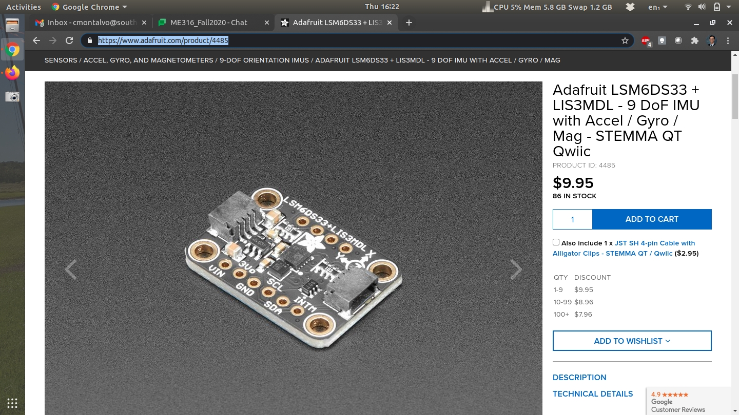
The sensor above is the Adafruit LSM6DS33+LIS3MDL. You basically have 2 separate microchips in one. The first (LSM6DS33) is a 3-axis accelerometer and 3-axis rate gyro. The first measures acceleration and the second measures angular velocity. The LIS3MDL is a 3-axis magnetometer which measures magnetic fields. If for some reason you don’t have this device in your kit you can purchase one on Adafruit for only $10 at the time of this writing. The interesting thing about this device is that you can actually purchase the LSM6DS33 and LIS3MDL separately but this breakout board has both chips on board.
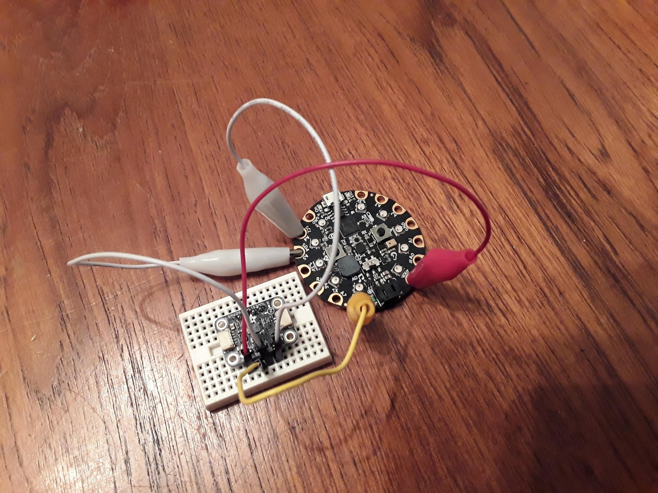
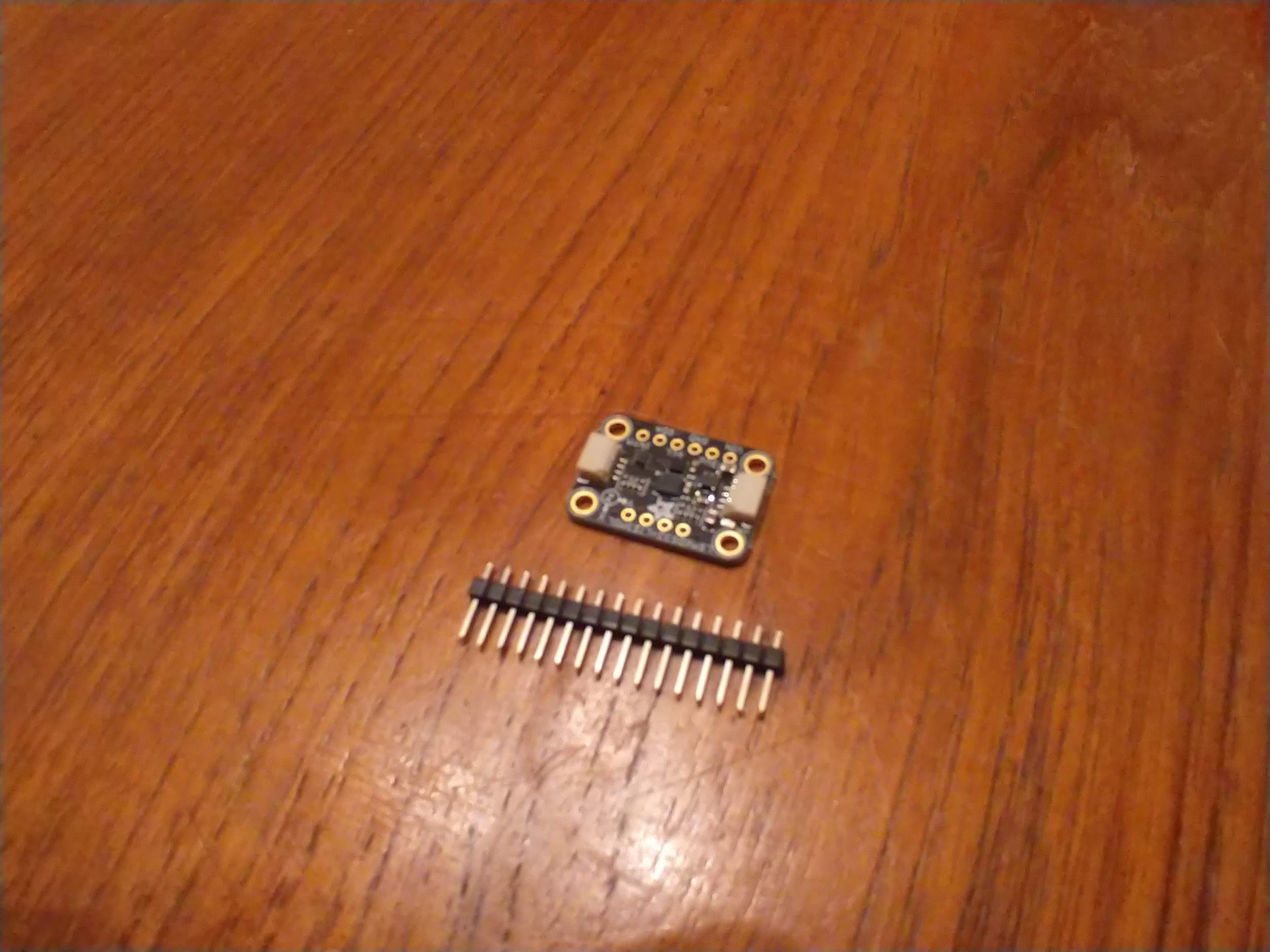
When you open the packaging of this breakout board you’ll notice that the header pins are missing. First you’ll need to cut a row of 4 and 6 for the top and bottom side of the board and solder the header pins to sensor. If you’re taking my class you can stop by my lab one day and I’ll solder this for you. If you are taking this class elsewhere you have two options: try and find someone who can solder this real quick (only takes about 5 minutes) or buy your own soldering iron and try to solder yourself. Using 4 alligator clips you need VOUT (5V) to run to (VIN), GND to GND and then SDA to SDA and SCL to SCL.
Believe it or not the photo above was actually wired wrong. I had SDA to SCL and SCL to SDA. You need to make sure you have the proper wires going to the correct pins or it won’t work. SDA and SCL are 2 pins for something called I2C (pronounced I squared C) where I is I as in "I am a billy goat" or "I like to code". I2C is beyond the scope of this project but just know it’s a type of serial communication that uses hexadecimal addresses.
Once you have the circuit wired and soldered it’s time to work on software. First want to make sure you have your Circuit Python UF2 up to date. In this example I’m using the 6.X version. Once I updated my UF2 I also updated my Circuit Python Libraries. The Circuit Python Libraries download as a zip file. You need to unzip the folder and go into the lib folder and grab the following python modules.
adafruit_bus_device
adafruit_register
lis3mdl
lsm6ds33
There will be folders for some and just floating .mpy files for others which are python modules that you can import just like time, board and busio as we’ve done in the past. Put those files into your lib folder on your CIRCUITPY drive. If the lib folder doesn’t exist you just need to make one. Once you have the necessary modules you can run some example code. The Adafruit Learn page has a tutorial for the LSM6DS33. The problem with the tutorial is that it seems like it was written for the Raspberry or some other microcontroller. As such I had to find some example code on Adafruits Github. After following both tutorials I was able to make my own script and upload it to my Github.
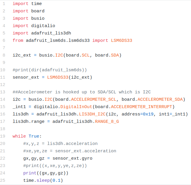
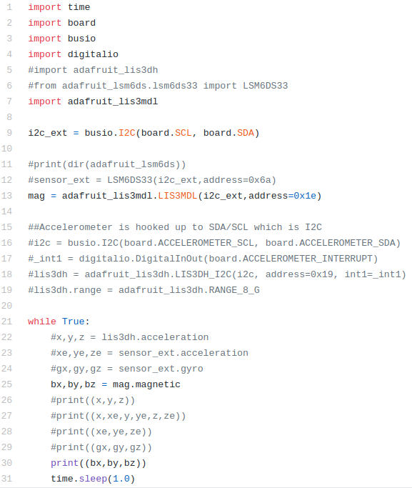
In the code above lines 1-6 import all the modules with line 5 importing the accelerometer on board the CPX and line 6 importing the external sensor wired up to SDA and SCL. Line 8 creates an I2C object using the SDA and SCL pins from the alligator clips and line 11 creates the sensor object. I also include lines 14-17 to include the onboard accelerometer. Notice I can access both sensors no problem. In the while loop line 20 checks the accelerometer on the CPX, line 21 checks the accelerometer on the breakout board and line 22 checks the angular velocity on the breakout board. Lines 23 and 24 print to serial and output to the plotter. Note that some lines are commented out because I wanted to try one thing at a time.
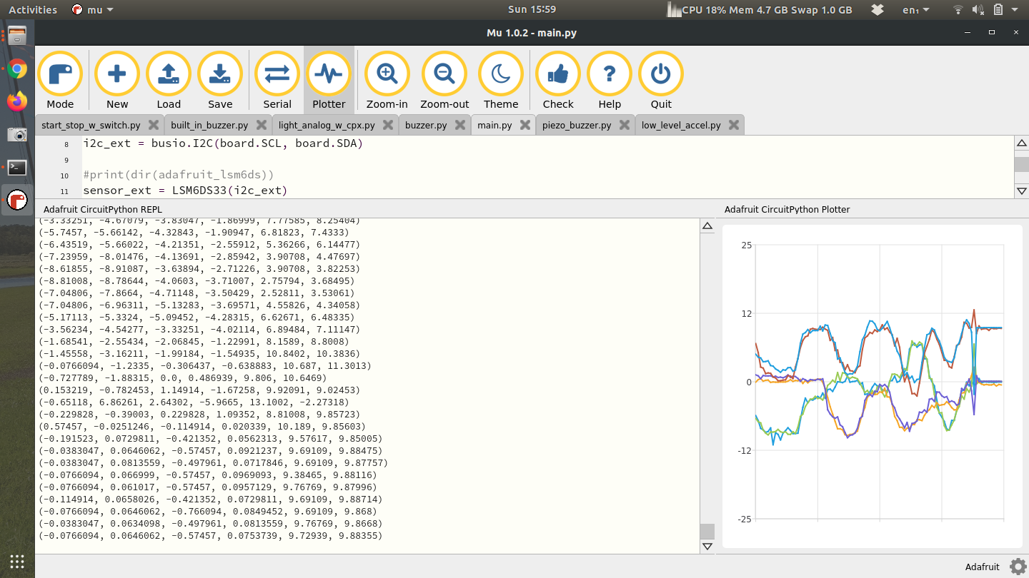
With both accelerometers printing to the Plotter I could move the CPX and the breakout board in unison and get the following output.
Notice that there are 6 numbers printed and 6 lines on the plotter. Both the CPX and the breakout board have little XYZ cartesian coordinate systems. I had to line them up properly before I started moving them. My suggestion would be for you to get some hot glue or 3M tape and place both breakout board and CPX on some sort of hard material like plywood, masonite, or even a cutting board. Anything to keep everything together.
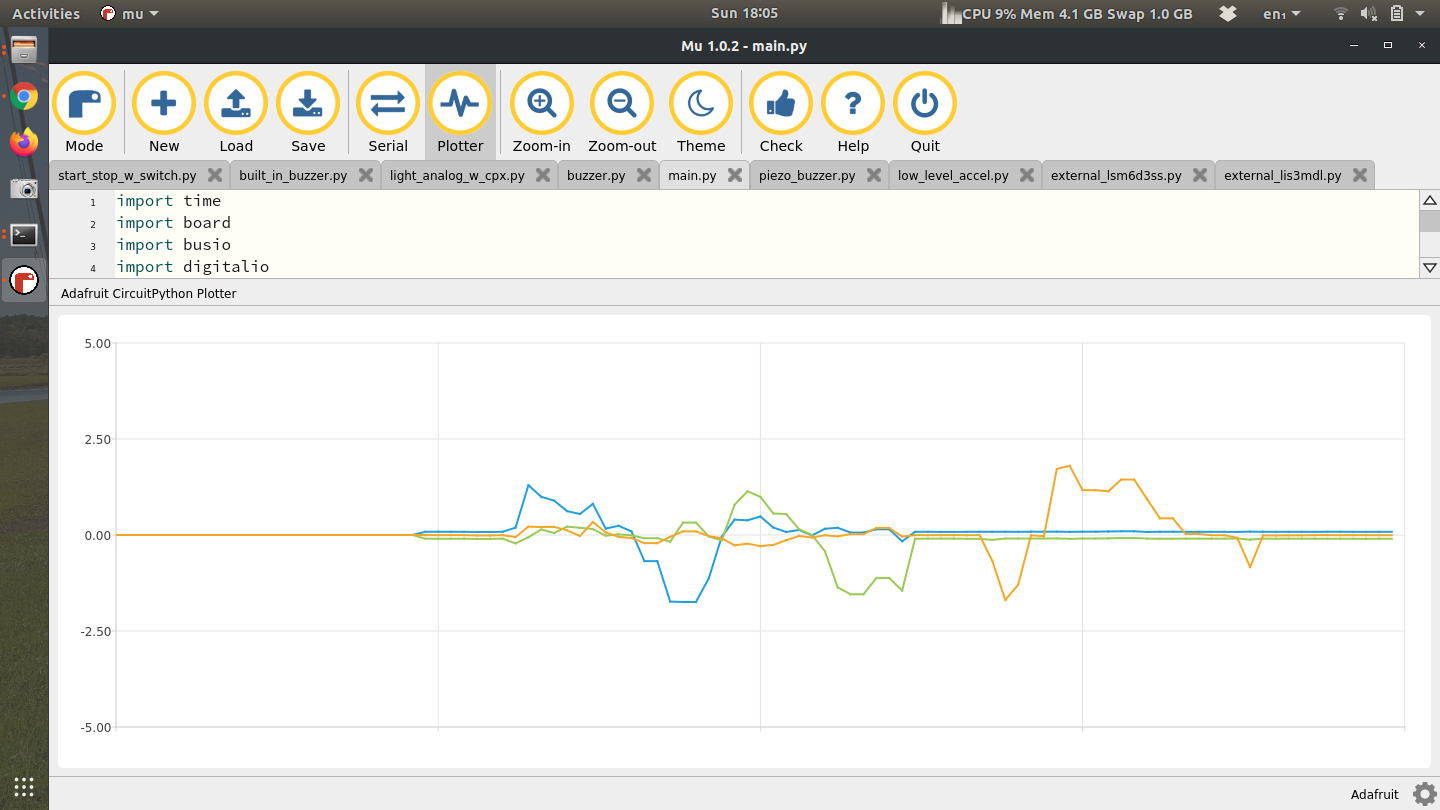
Once you’ve done this, try uncommenting the line of code that prints the angular velocity. When I do that and move the breakout board around I can measure the angular velocity of each axis. The units are in radians per second but it’s pretty obvious just from the magnitude of the graph.
The final part is to get the LIS3MDL (magnetometer) to work. The starting point for me was the Adafruit Learn page, along with the simple example from Adafruits Github. After that I was able to create my own co my own code. The only difference in your code is that the address will be 0x1c instead of 0x1e.
The code is almost identical to the code before except all the LIS3DH and LSM6DS33 code is commented out. Instead I have code to grab the magnetometer (LIS3MDL) at address 0x1E. Line 25 then calls the magnetometer and prints it.
Turning in this assignment
Include a video of you reading both accelerometers and generating a plot like I did. Plotter is fine for this portion - 10%
Include a video of you getting the magnetometer to work and plotting the data in the plotter as you move the magnetometer. - 10%
Create a pendulum for your “cutting board” circuit and swing the pendulum. Include a video describing your pendulum - 20%
While swinging the pendulum record the accelerometer on the CPX and the breakout board as well as the angular velocity. Plot the angle (theta) using both accelerometers. You will have 2 lines since there are two accelerometers. Also plot the angular velocity of the pendulum. Plot these in Python - 20%
Take the two theta values and use the finite difference method to take a derivative and get the angular velocity. Plot the derivative of theta alongside the angular velocity and comment on the similarities and differences. - 20%
Finally, take the angular velocity and integrate using a Reimann sum to get theta from integration and plot it alongside your two other values of theta from the accelerometers. Comment on the similarities and differences - 20%
Last updated