5. Assembly
This project involves some assembly by the students, including screwing hardware, plugging in wires, and gluing wooden pieces. Before assembling the device, please note that the laser cut system requires that the hardware on the left tower piece be mounted before gluing the pieces together. This step is crucial because it is nearly impossible to adjust the mounting hardware after the pieces are glued in place.
4.1 Tools and Preparation
Before beginning the assembly of the T-RECS, a few tools are required:
#2 Phillips Head Screwdriver (Required)
Needle-Nose Pliers (Recommended)
Scotch or electrical tape (recommended)
Tools can be ordered online or found at most Maker Spaces. It is also recommended that students verify the proper fit of the components with the mechanical parts before beginning assembly. Assemble wooden pieces without glue first to ensure that the pieces fit and are in the proper location and orientation. Check that the shafts possess a very secure fit within the arm and sensor and a satisfactory fit within the ball bearings. Additionally, check that the bearings also fit comfortably within both towers. If any of these components do not fit due to the mounting holes being too small/tight, sandpaper can be used to expand the hole, sand the shafts, and improve the fit.
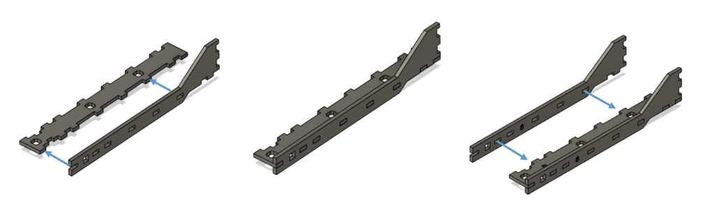
4.2 Wood Structure and Hardware
Note: the stopper and clip are now separate parts, the stopper (L-shaped piece) goes between the clip and the wood.
4.3 Insert Ball Bearings, Shafts, Arm
Pictorial clarification for inserting ball bearings, shafts, and arm.
Test the fit of the shafts into the arm. The 3D printed parts are designed to fit tightly into the wood parts and position sensor, but it may be necessary to remove and adjust the shafts later. It is very likely that the square sections of the shafts will need to be sanded a little to fit into the arm.
Insert the Ball Bearings from the inside of the towers.
Hold the arm between the towers, and slide the shafts in from the outside. Be sure that the shaft with the arm is inserted into the same tower that houses the standoffs (and later PCB). Insert the shaft with the arm such that the flat part of the semicircle is facing the back of the arm.
4.4 Add PCB, Adapter, and Microcontroller
Affix PCB to the standoffs with the M3 screws. Ensure the arm of the shaft is inserted into the position sensor.
The Raspberry Pi Pico and adapter are packaged together. The Pico can be pulled strait off of the adapter to be used on other projects later if desired (be careful not to bend the pins!). The male headers on the back of the adapter will slide directly onto the female headers on the PCB.
4.5 Attach Motor
It is easiest to slide the motor in from the bottom of the clip, and then make sure that the motor is barely touching the stopper at the bottom of the clip.
String the wires under the bridge of the top of the towers and plug them into the PCB.
(Optional, but recommended) Use tape to ensure the wires stay in place in the groove of the arm.
4.6 Plug In Wires
Plug the USB cord into the Raspberry Pi Pico and a computer, plug the power supply into the barrel jack on the PCB and to a standard outlet.
Last updated